Blueprints and Schematics for Homemade Microphones
Table of Contents
Building your own microphone isn’t just a hobby project. It’s one of the fastest ways to understand how audio actually works at a physical and electrical level. Most people buy microphones without ever thinking about what’s happening inside the casing. When you start working with blueprints and schematics, that black box becomes something you can control, modify, and improve.
This guide breaks down microphone schematics in a way that connects theory with real builds. You’ll see how different microphone types are designed, how circuits shape sound, and how to choose the right blueprint depending on what you’re trying to achieve.
Understanding How a Microphone Works Before You Build One
Every microphone follows the same fundamental process. Sound waves hit a diaphragm, the diaphragm moves, and that movement gets converted into an electrical signal. What changes between microphone designs are how that conversion happens and how the signal is processed afterward.
In a condenser microphone, the diaphragm interacts with an electrical field, which makes it highly sensitive and detailed. In a dynamic microphone, movement within a magnetic field generates the signal, making it more durable but less sensitive. Ribbon microphones use an ultra-thin metal strip suspended in a magnetic field, capturing sound with a unique smoothness that’s hard to replicate.
When you’re looking at schematics, you’re not just seeing wires and components. You’re seeing how that raw vibration gets shaped into something usable. That includes amplification, impedance matching, and noise reduction, all of which affect how the microphone actually sounds.
Core Components in Any DIY Microphone Blueprint
Microphone Capsule
The capsule is where sound becomes electricity. It’s the most important part of your build and the biggest factor in sound quality. Cheap capsules tend to introduce noise and lack clarity, while higher-quality ones capture more detail and frequency range.
Circuit and Signal Path
Once the signal is generated, it travels through a circuit that shapes and amplifies it. This is where schematics matter most. The circuit determines how strong the signal is, how much noise gets introduced, and how accurately the sound is preserved.
Power Supply
Some microphones require power to function. Condenser microphones often rely on phantom power, typically 48V supplied through an XLR cable. Simpler builds may use batteries, but that comes with limitations in performance and consistency.
Output Connections
The output stage determines how your microphone connects to other equipment. XLR is the standard for professional audio, while USB-based designs integrate digital conversion directly into the microphone.
Microphone Schematics Explained (What You’re Actually Looking At)
A microphone schematic is essentially a map of signal flow. It shows how electricity moves through the system, from the capsule to the output. Each symbol represents a component, such as resistors, capacitors, or transistors.
Understanding these diagrams isn’t about memorizing symbols. It’s about recognizing patterns. For example, capacitors often shape frequency response by filtering certain signals. Resistors control current and voltage levels. Transistors amplify weak signals so they can be used in recording equipment.
Once you start seeing these relationships, schematics become much easier to follow. You’re no longer copying a design blindly. You’re understanding why each component is there and how it affects the final sound.
Blueprints for Main Microphone Types
Condenser Microphone
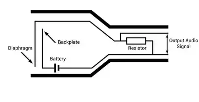
Condenser microphones are one of the most popular DIY builds because of their sensitivity and clarity. The blueprint typically includes a capsule connected to a field-effect transistor, which acts as the first stage of amplification.
The circuit then routes the signal through additional components that stabilize voltage and reduce noise. Phantom power is introduced through the XLR connection, supplying the energy needed to maintain the electrical field inside the capsule.
What makes this design powerful is its ability to capture subtle details. However, that sensitivity also means it’s more prone to noise if the circuit isn’t properly shielded. A well-built condenser microphone requires careful attention to grounding and component quality.
Dynamic Microphone
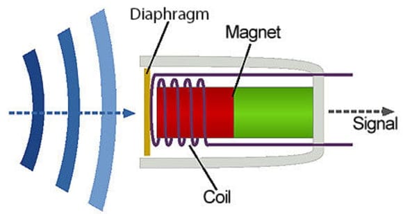
Dynamic microphones are mechanically simpler, which makes them easier to build and more forgiving for beginners. The blueprint focuses on a coil attached to a diaphragm, placed within a magnetic field.
When sound hits the diaphragm, the coil moves, generating an electrical signal. The circuit is minimal compared to condenser designs, which reduces the risk of noise and interference.
This simplicity is why dynamic microphones are widely used for live sound. They can handle high sound pressure levels and don’t require external power. For DIY builders, they offer a straightforward entry point into microphone construction.
Ribbon Microphone Build
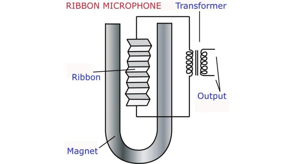
Ribbon microphones are more complex and delicate. The core of the design is a thin metal ribbon suspended between magnets. When sound waves hit the ribbon, it vibrates and generates a signal.
The blueprint includes a transformer that boosts the extremely low output signal to usable levels. Without it, the microphone would be too quiet to function in most setups.
Building a ribbon microphone requires precision. The ribbon itself is fragile, and even slight mistakes in tension or alignment can affect performance. However, when done correctly, the result is a smooth, natural sound that’s highly valued in recording environments.
Wiring Diagram for Homemade Microphones
Wiring is where many DIY builds fail. Even a well-designed circuit can produce poor results if the wiring isn’t handled correctly.
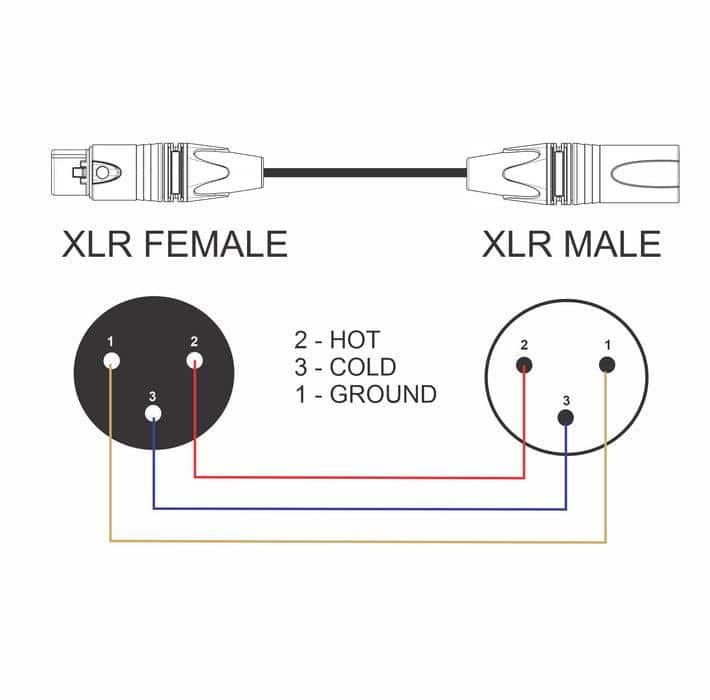
XLR connections follow a standard configuration. Pin 1 is ground, pin 2 carries the positive signal, and pin 3 carries the negative signal. Maintaining proper polarity is essential for balanced audio, which helps reduce noise over long cable runs.
Shielding also plays a major role. Poor shielding allows interference from external sources, which can introduce hum or static into your recordings. Using proper grounding techniques ensures that unwanted noise is minimized.
Common Mistakes When Following Microphone Schematics
Incorrect Grounding (Ground Loops)
Ground loops happen when multiple grounding paths exist, creating a circular path that picks up electrical interference. This typically results in a persistent hum that doesn’t go away, no matter how clean your components are. A proper microphone build should use a single, intentional grounding path so that unwanted noise has nowhere to accumulate.
Using Wrong Component Values
Every resistor, capacitor, and transistor in a microphone circuit is chosen for a reason. Swapping values, even slightly, changes how the circuit behaves. That can affect gain levels, frequency response, and overall clarity. In some cases, the microphone will still work, but it will sound noticeably off, either too weak, too distorted, or lacking detail.
Poor Shielding and Cable Choice
Unshielded wires or low-quality cables allow external interference to leak into your signal path. This becomes especially problematic in condenser microphones, where sensitivity is high. Without proper shielding, your microphone can pick up hum from nearby electronics or even radio frequency interference.
Messy Internal Layout
Internal wiring that is too long, tangled, or poorly routed increases the chance of interference. When signal wires run too close to power lines or cross unnecessarily, noise can be introduced into the circuit. A clean, compact layout helps maintain signal integrity and reduces unwanted artifacts.
Incorrect XLR Wiring (Pin Mistakes)
Swapping Pins 2 and 3 won’t stop the microphone from working, but it will invert the phase of the signal. This becomes a problem when using multiple microphones, as phase issues can cause a thin or hollow sound. Miswiring Pin 1, which is ground, usually results in immediate noise problems.
Ignoring Phantom Power Requirements
Condenser microphones depend on phantom power to function correctly. If the circuit isn’t designed to handle 48V and it’s applied anyway, components can fail. On the other hand, if phantom power isn’t supplied when needed, the microphone simply won’t operate as intended.
Weak Soldering Connections
Cold or poorly made solder joints create unstable electrical connections. These can lead to intermittent audio issues such as crackling, dropouts, or complete signal loss. Over time, weak connections tend to worsen, making the microphone unreliable.
How to Improve Sound Quality in DIY Microphones
Start with a High-Quality Microphone Capsule
The capsule defines how accurately sound is captured. Low-quality capsules often introduce hiss and lack detail, while better ones provide a wider frequency response and cleaner signal. Upgrading the capsule alone can dramatically change the final output, because everything downstream in your circuit depends on the quality of this initial signal.
Refine the Circuit Design for Cleaner Signal Flow
A well-designed circuit minimizes noise and preserves detail from the capsule. Using properly matched resistors and capacitors ensures stable voltage and consistent performance across different recording conditions. When the circuit isn’t optimized, you’ll often hear distortion, uneven gain, or a weak signal, even if the capsule itself is capable of much better results.
Upgrade Key Components (Capacitors, Resistors, Transistors)
Higher-quality components reduce internal noise and improve signal accuracy. Low-noise transistors, precision resistors, and better-grade capacitors help maintain clarity, especially in condenser microphone builds where sensitivity is high. These upgrades don’t just improve sound slightly. They can noticeably tighten the signal and reduce unwanted artifacts.
Use Proper Shielding and Grounding Techniques
External interference is one of the biggest threats to sound quality. Without proper shielding, your microphone can pick up hum, buzz, or even radio signals. Using shielded cables and ensuring correct grounding prevents interference from entering the signal path, which keeps your recordings clean and consistent.
Add or Pair with a Quality Preamp
DIY microphones often produce weaker signals, particularly ribbon designs. A good preamp boosts that signal to usable levels without adding noise or coloration. This makes recordings sound fuller and more controlled, especially when capturing quieter sources or subtle details.
Optimize Internal Layout and Wiring
Keeping wires short, organized, and separated from power lines reduces interference inside the microphone itself. A clean internal layout improves signal integrity because it limits opportunities for noise to be introduced. Even small adjustments in wire routing can make a noticeable difference in overall clarity.
Improve the Microphone Housing and Acoustics
The body of the microphone affects how sound waves reach the capsule. Poor housing design can create internal reflections or unwanted resonance, which colors the sound. A well-designed enclosure helps maintain a more natural and balanced frequency response.
Fine-Tune Capsule Positioning and Orientation
Small changes in how the capsule is mounted can affect sensitivity and frequency response. Proper alignment ensures that sound waves hit the diaphragm evenly, which improves consistency and avoids tonal imbalance. This becomes especially important when recording vocals or detailed acoustic sources.
Control Environmental Factors During Use
Even a well-built microphone can sound poor in a noisy or reflective environment. Using pop filters, shock mounts, and proper placement helps reduce unwanted noise and maintain clarity. The surrounding space plays a bigger role than most people expect, so optimizing your recording environment is just as important as the microphone itself.
Choosing the Right Blueprint Based on Your Goal
The right microphone blueprint comes down to how you plan to use it and how much complexity you’re comfortable handling. Different designs prioritize different strengths, so matching the build to your actual use case will save you time and frustration.
For Podcasting and Voice Recording
A condenser microphone design is usually the best fit. It captures more detail and clarity, which helps voices sound fuller and more professional. This makes it ideal for spoken content where nuance and presence matter.
For Live Sound or Rugged Environments
A dynamic microphone blueprint is the more practical choice. These designs are more durable, less sensitive to background noise, and can handle higher sound pressure levels without distortion. They’re better suited for unpredictable or untreated environments.
For Studio-Quality Recordings With Character
A ribbon microphone offers a more natural and smooth sound profile. It’s often preferred for music recording, especially for vocals and instruments where warmth and tonal depth are important. However, it’s also more delicate and complex to build.
For Beginners or Simple Builds
Starting with a dynamic microphone or a basic condenser schematic is usually the smartest move. These designs are easier to assemble and troubleshoot, which helps you understand the fundamentals without getting overwhelmed.
For Advanced Builders and Customization
More complex condenser or ribbon schematics give you greater control over sound shaping, but they require a deeper understanding of circuits and components. These builds are better suited if you want to experiment and fine-tune performance.
Choosing the right blueprint isn’t just about sound quality. It’s about balancing performance, durability, and build complexity so the final result actually fits your needs.
Frequently Asked Questions
What is the easiest DIY microphone to build?
Dynamic microphones are typically the easiest because they require fewer components and don’t need external power. Their simple design makes them ideal for beginners.
Can you build a professional-quality microphone at home?
Yes, but it depends on component quality and build precision. High-end capsules and well-designed circuits can produce results that compete with commercial microphones.
Why do condenser microphones need phantom power?
Condenser microphones rely on an electrical field to operate. Phantom power supplies the voltage needed to maintain that field and power internal circuitry.
How do I reduce noise in a homemade microphone?
Proper shielding, correct grounding, and high-quality components are the most effective ways to reduce noise. Paying attention to wiring layout also helps prevent interference.
Are USB DIY microphones worth building?
They can be useful for convenience, but they add complexity because they require analog-to-digital conversion. XLR designs are often preferred for flexibility and sound quality.


